


By Kevin Kalmus
Apparatus Operator, Austin Fire Department
If you are the assigned apparatus operator for your department and have your hydraulic pump chart memorized, this article is not for you.
For the rest of us who struggled not to fall asleep in high school algebra, here is your scenario. Its 3 a.m. and your Engine Company just arrived on scene as part of a second alarm complement at a large warehouse fire.
Your unit’s assignment is to protect exposures on multiple sides of the fire building. As soon as your apparatus is positioned and a hydrant is secured, lines are being deployed in multiple directions.
Your two 200-foot preconnected Speedlays, which are connected to the number one and two Speedlay outlets, are being deployed to protect some nearby homes. Each line consists of a 1¾-inch hoseline, one with 175-gpm at 75-psi fog nozzle and the other a 15/16-inch smoothbore tip.
A 300-foot 2½-inch Crosslay line has been attached to the number one 3-inch discharge on the driver’s side and has a 11/8–inch smoothbore nozzle. A Rapid Attack Monitor (R.A.M.) attached to 400 feet of 3-inch supply line has been placed on the roof of a two-story building to flow down on the roofs of the adjacent exposure buildings.
The line is attached to the number four driver’s side discharge. A “bundle” line consisting of two 150-foot 2-inch hose lines with 1-inch smoothbore tips have been stretched to the Bravo side of the warehouse.
The two lines are connected by a wye appliance to 300-feet of 3-inch line, which is attached to the number three 3-inch outlet on the passenger side of the apparatus.
Finally, a highway/bumper line consisting of 150 feet of 1¾-inch hose with an 85-psi automatic nozzle has been deployed to protect a truck company that parked too close to the fire building and its light covers are beginning to melt.
Out of that entire scenario, the only numbers I can remember are 3/11/05 — and that’s because it’s my wedding anniversary and my wife can be much scarier than any warehouse fire.
So what’s the solution for those firefighters who, like me, can’t keep all those numbers straight? The first step is to have an easy to use and readily available hydraulic pump chart, as seen above right.
However, let’s be honest — even departments that keep up-to-date charts on every apparatus rarely use them, and when they do, it’s normally one or two numbers that are used ninety percent of the time.
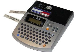
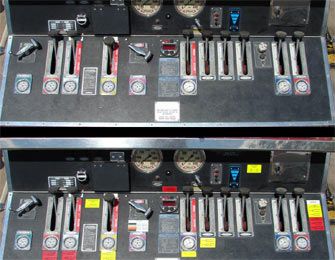
A quick answer to the problem of ensuring your pump operators are using the correct discharge pressures is to place the most commonly used parts of the hydraulic pump chart on the pump panel itself. A label maker found in most office supply stores is an inexpensive solution to placing information on the pump panel, as seen below.
 |
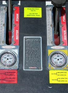
Most manufacturers make a laminated label that is designed for outdoor use. Give the pump panel a more professional look by using clear labels and placing them on the same reflective material used for apparatus striping:
 |
A good rule of thumb, when considering what information to place on the pump panel, is to use the 90/10 rule. Place the discharge pressures that are used ninety percent of the time near the discharge gauges associated with those pressures and the other ten percent, the pump operator will need to reference from the pump chart.
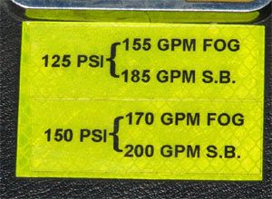
The numbers that should be placed on the panel are determined by the individual department’s hose and nozzle setups. The first number should be the ideal gpm flow for the nozzle. For instance, a 15/16" smoothbore nozzle at 50-psi nozzle pressure is designed to produce 185-gpm.
If this is the nozzle carried on a preconnected line, the first number should show the required discharge pressure to flow 185-gpm. The second number should be a balance between the maximum gpm flow that two firefighters can handle and an acceptably performing water stream. See the image below:
 |
With a two-pressure set up, instead of multiple requests to increase pressure coming from the nozzle team, one radio transmission allows the team to ask for the maximum amount of water they can handle.
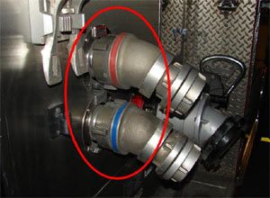
Another common problem many apparatus operators encounter is trying to remember which discharge a hose line is attached to. Was it the #1 Discharge, the #1 Speedlay, or the #1 Crosslay that needs to be charged?
NFPA 1901 states that all discharges be color coded and labeled to correspond with the appropriate discharge gauge on the pump panel, but does not specify what type of markings are required.
Many apparatus manufacturers use small colored labels glued above the individual discharges and gauges to meet the standard, as seen in the following photo. Older apparatus often are found to be missing the labels, or they have faded due to exposure.
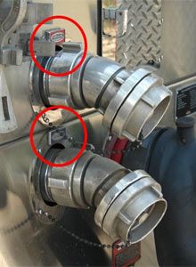 |
A quick and inexpensive solution to solve this problem is colored electrical tape. Studies have also shown that individuals under stress can more easily remember a color than a number.
Wrap the tape around the discharge outlet and the pump operator does not even need to get close to the outlet to determine which discharge the hoseline is attached to:
 |
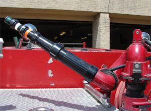
Finally, many apparatus operators find it difficult to determine the size of the tip when looking up at an apparatus-mounted deck gun, equipped with a set of smoothbore stacked tips.
By combining the label maker and electrical tape, a quick reference guide can be placed on the pump panel that correlates with the deck gun tip sizes. Take a look at the two photos here:
 |
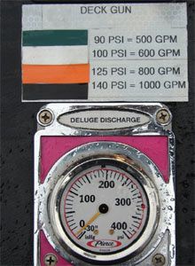 |
Wrap colored tape around each section of the stacked tips. Use the tape and label maker to create a color-coded chart identifying the discharge pressures needed to achieve the standard 80 psi nozzle pressure for a smoothbore master streams.
The chart will give the pump operator an easy to use visual guide that allows them to flow between 500 and 1000 gallons per minute on most apparatus.
So just like we had to do in high school algebra, after sleeping through a couple lessons, let’s make what can be a very challenging job a little bit easier by setting up the pump panel with a “cheat sheet:"
 |
Kevin Kalmus is an apparatus operator with the Austin Fire Department, assigned to Engine 22 in the South East district. He has a bachelor’s degree in government from Georgetown University, a master’s degree in molecular biology from the University of Texas, and is an adjunct instructor for the Austin Fire Department’s recruit academy and driver/operator and professional development programs.